
by W.A. Steer PhD

A "video-digitiser" (also known as a "frame grabber") captures still frames from a TV set, video camera,
or video recorder, etc., and forwards them to a computer for display,
storage, or general manipulation. This document describes the MarkII version of
a home-built digitiser which interfaces to an EPP parallel port on IBM PCs.
MkII supports colour captures (PAL/NTSC decoding in software).
Note: the Bt218 chip, around which this project is based, ceased to
be manufactured during the year 2000. If you want to build this project as
shown, ensure you can get some old stock! Alternatively, you could adapt
the circuit to work with a different low-cost ADC, such as the TDA8703 from Philips.
I have not done this myself yet, so cannot offer details.
You might also want to check out my earlier
(Mk1) digitiser page, which includes more background information, particularly on video signals and timing.
MkII Video digitiser - Specification
-
Odd/even single-field still image capture from 50/60Hz PAL/NTSC composite video
sources
-
Connection to host computer via PC parallel port (EPP)
-
12-15MHz pixel clock (depending on crystal/osc), giving images ~730 by 288 pixels.
-
Eight bits per pixel sampling, colour decoding in software.
-
Maximum capture rate 3 fields per second typ. (non-compressed)
-
Very high quality PAL colour decoding in software (not real-time, few seconds
per image). NTSC colour in pipeline!
-
Requires low voltage power supply (circuitry runs off +5V dc internally), 200mA typ.
-
Total electronic components cost (one-offs): approx. 50 pounds sterling as at April 1999. Add extra for circuit boards, boxes, cable, connectors, power supply, etc., if required.
-
Software supplied:
- Image capture (16-bit application) to work under Win31, Win95/98, WinNT.
- [Image capture (32-bit application) Win95/98 ONLY]
- Prototype colourisation (32-bit app) for Win95/98/NT (requires at least 32768-colour display settings).
- Source-code extracts to help creation of your own custom software
Any PC hardware capable of running the operating systems mentioned should run the
software adequately, though as always, a faster PC will often result in better
performance. In particular, colourisation will be very slow on anything sub-Pentium!
An EPP-type parallel port is required (though with software modifications, a simple
bi-directional port would be useable, with poorer speed)
The principal improvements over Mk I are
- uses a full-field memory buffer
- removes need for messy line-selection logic
- makes circuitry and capture simpler and faster
- all the data from same field, so the image doesn't break up if the subject moves
- interline colour subcarrier phase relationships are largely preserved...
- output from the memory chip is properly buffered now - improve compatibility / reliability
- supports PAL/NTSC colour-decoding in software
- working software provided
Limitations:
- Still only captures one of the two interlace fields (though often the second one would lead to motion blur anyway...). Limited by mere 256kB of buffer. Published design captures odd/even field at random, though by simple modification you could ensure one or the other is guaranteed.
- Digitisation clock arrangement shown is not fully phase-locked to the linesync. A proper
line-locked sampling clock could quite easily be implemented as an extension to the project.
Notes:
- this design has been optimised primarily for picture quality for single-frame grabs, given circuit simplicity and reasonable cost considerations
- In general, horizontal resolution is decreased in domestic video recording formats (and
colour is really seriously degraded). Use off-air signals from a good aerial for best
results!

Example colourised image, digitised, I think, from ITV's Cook Report programme,
7th February 1999. Off-air from the Crystal Palace transmitter, London.
(This image is from only one field, so the height needs to be doubled to obtain the correct aspect ratio). It was digitised with a
14.161Msps clock, partially phase-locked to the line-sync.
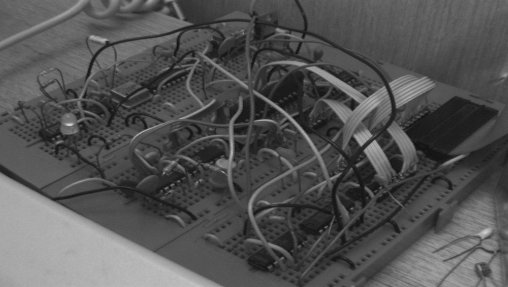
Digitiser in prototyping (image from b&w TV camera, captured by the
very hardware featured)
Technical
Block diagram and overall description
The ADC converts the incoming composite video signal to a digital representation,
sampled typically at 15MHz. This data rate is far too fast for the parallel port to
cope with directly, so instead the circuitry is arranged so that data from ADC is
fed into a high-speed 256kB field memory. Video timing logic uses line and field
synchronisation signals from the sync-separator to ensure that storage begins
and ends at field boundaries, and that a fixed number of samples (pixels) are
collected for each video scan line. PC parallel port interface logic controls the
output of data from the field memory to the host PC, and temporarily halts the
refreshing of the image in the memory while data is being read out.
(see the original digitiser page for discussion of composite video signals)
Detailed circuitry
Table of ICs
| IC 1 | EL4581CN | Video sync separator | Elantec (near-equiv from National) |
| IC 2 | 74HC14 | Hex Schmitt inverting buffer | Texas/National/Motorola |
| IC 3 | 28.322MHz osc. | Quartz oscillator module | AEL / EuroQuartz | * see text for alternatives |
| IC 4 | 74HC4040 | 12-bit async. binary counter | Texas/National/Motorola | * dependent on clock arrangement |
| IC 5 | 74HC74 | Dual 'D' latch with set/reset | Texas/National/Motorola |
| IC 6 | 74HC4017 | Decade counter | Texas/National/Motorola |
| IC 7 | Bt218KP-20 | 20Msps 8-bit video ADC | Brooktree (Rockwell Semiconductor) |
| IC 8 | MSM518221A-ZS-30 | 256kB field video memory | OKI semiconductor | ZIG-ZAG package! |
| IC 9 | 74HC14 | Hex Schmitt inverting buffer | Texas/National/Motorola |
| IC 10 | 74HC00 | Quad NAND gate | Texas/National/Motorola |
| IC 11 | 74HC541 | 8-bit data buffer | Texas/National/Motorola |
Notes
- Data sheets for the ADC and memory are available from their manufacturer's Websites
- Data sheets for the 74HC logic family are available in PDF format from the
Texas instruments website.
- The MSM518221A-3Z ??? is supplied in a "ZIG-ZAG" package, with two rows 0.1"
apart, of pins on 0.1" spacing, with the two rows offset by 0.05". This will not
be an issue if designing a PCB, but for breadboard or Veroboard construction you
will need to make an adapter!
For convenience, the circuit is drawn in three sheets: 1) showing the analog and
digital video signal path, including parallel port interface, 2) showing the clock
and video timing, 3) the voltage regulator.
Errata: In the diagram below, the connection to pin 12 of the Bt218 ADC
(clamp input) should come from pin 2 (the output) of inverter IC2a, not
from pin 1.
Diagram 1:Main circuit diagram, showing analog and digital signal paths.
Diagram 2:Clock, and video timing logic.
Diagram 3:Power supply.
Points to note:
- MSM518221 - WE enables data to be written and forward the Write pointer,
IE when low, allows the write pointer to be forwarded, but inhibits overwriting of data.
Reset Write Pointer (RSTW) is semi-synchronous - supposed to only lower for one cycle at
a time - does NOT hold the Write Pointer at the start indefinitely!!! This explains why
some of the WE logic is less simple than it might be. CAUTION if modifying my design!
- On the Bt218KP the colour subcarrier trap is shown with component values for UK standard PAL: for NTSC, use two 220pF capacitors in paralllel to make 440pF to attenuate the
3.5MHz signal. The subcarrier trap is ONLY required when obtaining black-and-white captures
from colour signals, or when the sampling rate is too low to sample Fsc properly (eg less than 12MHz).
- IC5b ensures that data collection starts/stops only on field boundaries. The D latch is
clocked on the field-sync, with data input (enable/disable collection) being derived from
whether or not data is in the process of being downloaded to the PC.
- The logic (part of IC9 and IC10) to the right of Sheet1 are concerned with creating an
EPP-compatible interface to the parallel port. IC11, the 74HC541 eight-bit buffer, buffers
the output data to the computer, giving sufficient drive on the cable. NOTE: data lines to the PC should be fitted with 4k7 hold-down resistors (not shown). More information on EPP
interface is to be found in my original digitiser write-up.
- Sheet2 shows one possible configuration for the clock and enable logic. IC6 has a special task in that it counts past the first 10 "lines" - some of which are in reality
only half length - and inhibits collection of those - otherwise the captured picture would
sometimes wrap-around. Reset logic to IC4 is a crude attempt to give pseudo line-locking of
what is essentially an asyncrohous clock. IC5a in conjunction with the binary counter output
ensures a controlled number of samples are made per video line [timing diagram required].
- Sheet3 should be self-explanatory. The low-voltage PSU should be capable of delivering
at least 200mA. If the input voltage exceeds say 12V, heat dissipation in the 7805 may become a
problem.
Sampling clock rates
In practice, any sampling clock rate in the region of 12 to 15MHz will give
adequate results. However, various optimisations may be desireable:
- In theory, to get a picture with "square pixels" (ie. perfect aspect ratio) a clock rate of 14.75MHz is required for PAL pictures (12.273MHz for NTSC).
- For colour decoding, there is some advantage to be gained from having a sampling clock which is an exact multiple (usually 3 or 4 times) of the colour subcarrier. For PAL, Fsc=4.43361875MHz, so 3Fsc=13.301MHz, and 4Fsc=17.734MHz. With NTSC, Fsc=3.579545MHz, so 3Fsc=10.738MHz, and 4Fsc=14.318MHz.
- There is also a CCIR international standard rate of 13.5MHz for digital video, but this is of little significance for this project.
- It is preferable to have an integer number of samples per line, to prevent pixel, or sub-pixel, interline horizontal jitter or drift. Since a horizontal scan lasts 64us, the total number of samples per line is simply 64 times the clock frequency in MHz.
- Clock rates faster than around 14.2MHz (depending on how much of the H-sync is stored) will result in too much data being collected to fit the full number of lines into the 256kB (262144byte) frame-buffer memory chip. [Would have to crop some lines from the top or bottom of the picture.]
There are digitiser clock-generator ICs on the market which generate line-locked
clocks of all the standard frequencies given a video signal. I did not opt to use
one of these owing to the cost, added complexity, and possible difficulty of
obtaining supplies.
My design was based on a crystal oscillator of 28.322MHz which I happened to have
to hand. When divided by 2, this gives 14.161MHz. Because this clock does not give
an integral number of samples per line, a "trick" was used: reset the divide-by-two
using the linesyncs - this reduces worst-case jitter down to 0.5pixel, rather than
1pixel. [I would like to try using a 14.750MHz (or 14.000MHz, 14.250MHz) clock
free-running (no line-resets), possibly with the crystal trimmed using a variable
capacitor to remove all horizontal skewing. This should tidy up the vertical edges
and improve colour decoding further... and simplify!]
Errata
Since putting this page on line, a couple of minor errors in the circuit
diagrams have been reported:
- Sheet 2: there is some uncertainty as to which pin of IC4 (74HC4040)
connects to IC5a. The 'Q3' designation doesn't tally with 'pin 5' shown.
It doesn't actually make much difference: connect to pin 5 and ignore
the errant Q-notation
- Sheet 1: the connection to pin 12 of the Bt218 ADC (clamp input) should
come from pin 2 (the output) of inverter IC2a, not from pin 1 as shown.
- Where should I connect "RE" and "OE" pins in the IC8(MSM518221A)?
RE and OE (pins 16 and 17) should both connect to +5V
-
My MSM518221A manual is too confusing. I have problems how to connect it.
If you have the ZIP (Zig-zag) package, then if you hold it with the
printed side facing you (there should be a small dot in the top-right
and bottom-left corners), then... The pins nearest you are the odd-numbered
pins, beginning 1,3,5,7... from the left. The back pins are 2,4,6,8,... also
from the left.
I was going to reproduce the diagrams a little larger and make the corrections,
but since the obsolecence of the Bt218KP, this probably won't happen.
Safety and cautionary notes
Legal disclaimer
This video digitiser is a fairly advanced project, and it is therefore assumed that anyone
considering building it has some substantial experience of electrical and electronic techniques.
I have applied reasonable care in the design and preparation of the circuitry, diagrams and
descriptive material, and have endeavoured to point out any particular hazards that might be
relevant. Nevertheless, it is always possible that mistakes or omissions have been made:
you take ultimate responsibilty for all consequences of building this project.
Specific precautions
- A computer is an expensive piece of equipment! It is highly advisable to experiment
using a parallel port on a (cheap and replaceable) I/O card than one built onto the motherboard
- though be sure to realise this precaution still does not make your PC 100% invincible.
- Most of the IC's used in the design are CMOS parts and can easily be damaged by static
electricity (as can the parallel port itself). Take all the usual ESD precautions when
constructing the circuit. Avoid modifying the circuit while it is plugged in to the computer
-- if you insist on doing so, then be absolutely sure to earth yourself (eg by touching the
metal case of your computer) immediately prior to every adjustment. Do not insert or remove
any IC from the circuit while power is applied.
- It is general good practice not to interconnect or disconnect separate pieces of electronic equipment while the power to any device is on.
- This is especially important if you are taking your composite video feed from a source, such as a television set, which is "double insulated" (not earthed). Due to faults/ageing of the TV power supply, its low-voltage circuitry, including the chassis 0v (ie the case/screen/0v
of the phono/BNC/SCART sockets) can in reality be resistively or capacitively coupled to the
mains, often enough to give a mild tingling in the fingers if touched!
If the TV is connected via the phono/BNC/SCART socket to something else which is earthed, such as a video recorder, or the digitiser (earthed via the computer), the TV will be indirectly earthed via the signal cable: this is not an ideal situation, but does not normally cause any major problems.
However if, with all power applied, you were to unplug that connection, and just say the 0v connector came apart before the signal (video/data etc), you could now be feeding 240Vac down
that signal line - potentially OUCH for all equipment concerned! Since the video signal is
probably terminated by a low value resistor at both pieces of equipment, that will probably
survive. But if your digitiser hardware is on a floating power supply and becomes high-voltage
via your TV, connecting the digitiser to the computer could be a bad move.
- If you are going to make interconnections with the power on, always connect the
digitiser circuit to the PC first, then connect to the additional equipment (TV) last.
For disconnection, do the reverse: disconnect the TV first.
- Worthwhile additional protection is gained by ensuring the sheilds of your D-connector
shells are not left floating, but are connected to the cable screens where appropriate, and
then the chassis of the socket on your digitiser is connected to your circuit ground (0v).
That way, when the circuitry is plugged into the parallel port, any high voltages (or charges)
present on the whole circuit should discharge harmlessly through the sheild (which should mate first) instead of through a data pin (ouch!).
- You should check my diagrams and be sure in YOUR OWN MIND that everything is safe, similarly
check any physical circuits you build against the diagrams BEFORE plugging in and/or applying
power.
Enjoy!
Software
A (16-bit) application to capture the images is available:
videodig.exe [68kB].
Download, save, and run it. This first release is permanently configured to use the
parallel port at base address 0x278 (usually LPT2). It is also permanently set for
840 pixels per line. This program should run on Win31, Win95/98, and WinNT4 platforms.
The complete source code for the above application is also available:
vidisrc.zip [10kB].
It was written using the old (Borland) Turbo C++ v3.1 for Windows 3.1 compiler
- which will be required to compile it in its entireity.
If you want to write your own software from scratch, the following extracts from my
C++ source code should show all the important steps you need to get started.
// Program to collect video-digitised pictures from the EPP parallel port
// Collects ONE FIELD at a time from MSM518221 frame buffer IC.

// (C) W.A.Steer 1998

#define VID_PIX 840          // pixels per line to collect
#define VID_LINES 304        // number of scan lines to collect


const int portbase=0x278;
const int status=portbase+1;
const int control=portbase+2;
const int eppdata=portbase+4;

int scanbuf[VID_PIX/2];  // (16-bit int)

// Initialise port control-output settings (for periods between EPP transfers)
outportb(control,36);


// Commence frame-grab

 // Reset the MSM518221 read-pointer
 outportb(control, 32);
 outportb(control, 36);

 for(int line=0; line<VID_LINES; line++)
 {
  // Get the data
  for(register int dpixel=0; dpixel<(VID_PIX/2); dpixel++)
   scanbuf[dpixel]=inport(eppdata);  // input 2 bytes in one operation

  // store the line in an image bitmap (custom-code)
  image->SetLine(VID_LINES-1-line, (BYTE *)scanbuf);
 }

 // insert code to display image on screen here
Colour decoding [PAL]
See Software PAL/NTSC decoding page.
Includes downloadable software!

|
|
If you're interested in developing your electronics skills beyond beginner, I can thoroughly recommend
you buy 'The Art of Electronics' by Horowitz and Hill. It's an extremely readable hands-on guide to practical electronics
and packed with real-world experience and know-how. Widely regarded as the 'bible' of electronics...
<<< Amazon.com | Amazon.co.uk >>>
|
|
Created: April 1999
Last modified: 12 June 2002
Source: http://www.techmind.org/vd/vidmk2.html
©2000-2001 William Andrew Steer
andrew@techmind.org