by W.A. Steer PhD
![]()
by W.A. Steer PhD
| Back to contents | About... |
![]()
A technical description of autostereograms, their geometry, and the algorithms and programs I developed for creating them.
While these demonstrated that a single-image stereogram was possible, there are three major problems with this empirical method:
These limitations can be overcome by studying the underlying geometry and adopting a more rigorous approach. I have taken as a starting point the core of the symmetric algorithm documented in "Displaying 3D Images: Algorithms for Single Image Random Dot Stereograms" by H.W. Thimbleby, S. Inglis and I.H. Witten. Readers of that paper will notice that I have used a more intuitive coordinate system, and should note that I develop my own hidden-surface and anti cross-linking methods which supercede earlier approaches.

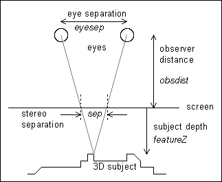
Figure 1: Geometry.
This "stereo separation" at the screen can be quantified by applying similar triangles, and assuming that the point on the object is straight ahead of the viewer:
sep = (eyesep * featureZ) / (featureZ + obsdist) [equation 1]Conversely, two similarly coloured points placed on the screen at this separation can represent a virtual point behind the screen. In this way it is possible to create an "autostereogram" which when suitably viewed, by diverging the eyes as if looking through the screen, reveals a 3D image.
Note that equation 1 is absolutely central to the process of generating stereograms with linear depth. Later references to z-resolution and permissable depths of field etc. are derived from that expression.
To start with, each point is `linked' to itself, purely to indicate that it is not linked to any other. Proper links are then calculated, working from left to right. Links are only recorded if both the left and right points are within the bounds of the picture, and are one way, i.e. the right-hand point of each pair references the left in the array lookL[], but not vice-versa. This is sufficient (at this stage) as we apply the random dots from left to right also.
 const maxwidth=640;
 int xdpi=75;    // x-resolution of typical monitor

 int width=640;  // width of display in pixels
 int height=480; // height of display in pixels

 int lookL[maxwidth];
 COLOUR colour[maxwidth]; // any type suitable for storing colours

 int obsDist=xdpi*12;
 int eyeSep=xdpi*2.5;

 int featureZ, sep;
 int x,y, left,right;

 for (y=0; y<height; y++)
 {
  for (x=0; x<width; x++)
  { lookL[x]=x; }

  for (x=0; x<width; x++)
  {
   featureZ=<depth of image at (x,y)>; // insert a function or
				       // refer to a depth-map here

   // the multiplication below is 'long' to prevent overflow errors

   sep=(int)(((long)eyeSep*featureZ)/(featureZ+obsDist));

   left=x-sep/2; right=left+sep;

   if ((left>=0) && (right<width)) lookL[right]=left;
  }
The second stage is to apply the pattern within the constraints imposed by the
links. This is quite simple and the program speaks for itself (random-dot
method):
  for (x=0; x<width; x++)
  {
   if (lookL[x]==x)
    colour[x]=<random colour>; // unconstrained
   else
    colour[x]=colour[lookL[x]]; // constrained
  }
The third stage is to plot the resulting pattern on screen.
  for (x=0; x<width; x++)
  {
   SetPixel(x,y, colour[x]);
  }
 }

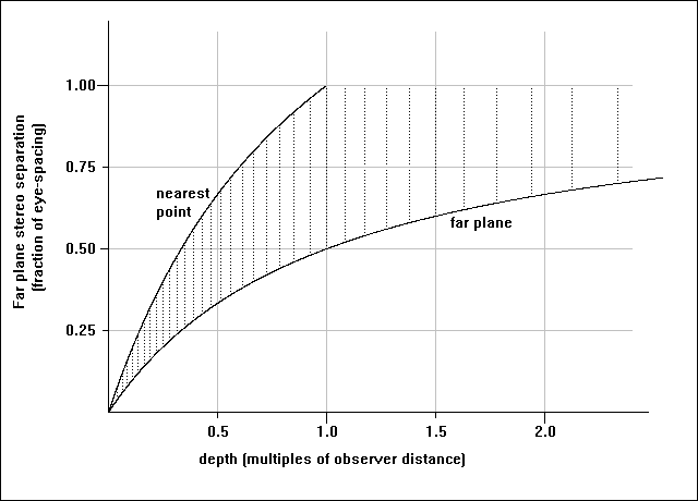
Graph 1: relation between stereogram depths and depth of field. The
dotted vertical lines show discrete depths representable with a 20dpi
display, and indicate the reduction of z-resolution with increasing depth.
Generally, a good starting point is to make the maximum depth equal to the observer distance. This gives a maximum stereo separation of half an eye-separation on which it is almost impossible to mis-converge the eyes, and permits the uninitiated to use their reflection from the surface as a guide.
From equation (1) it can be shown that the minimum permissible depth in the stereogram consistent with the first rule is given by:
mindepth=(sepfactor*maxdepth*obsdist)/((1-sepfactor)*maxdepth+obsdist)where sepfactor is the ratio of the smallest allowable separation to the maximum separation used. A typical value would be 0.55.
Of course in any particular stereogram the shallowest depth used does not have to be the absolute minimum allowable.
If the stereogram depth information will be obtained from a ray-tracer then it is a good idea to create the original scene with these constraints in mind, then the co-ordinate systems of the two processes can easily be interchanged and correct perspective obtained.
In that case, use:
featureZ=<distance of point behind screen according to ray tracer>Alternatively, if a depth-map height-function is used then the following formula should be used:
featureZ=maxdepth-h(x,y)*(maxdepth-mindepth)/256where h(x,y) is a height function with values from 0 (farthest) to 255 (nearest). h may be obtained from a grey scale depth-map picture,
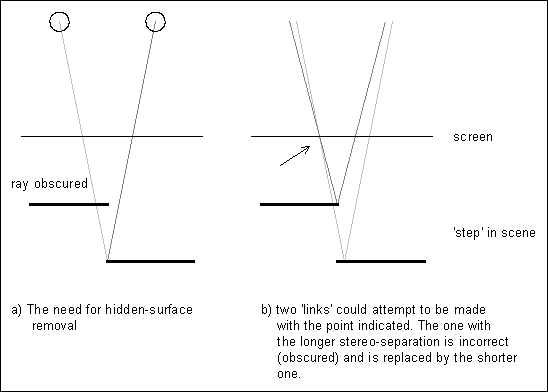
The problem arises because links are made even for points on the object that are only visible to one eye. In the case of the depth getting shallower in a rightwards direction, incorrect links tend to be overwritten with good ones. When the depth gets deeper rightwards, bad links overwrite good. The resulting mixture of good and bad links means that some `left' points can be referred to by two or more `right' points. Such double-linking leads to depth-ambiguities (the `flange'), and because the stereogram process can only correctly support unique depths, the flange becomes repeated with the rest of the pattern and spoils the picture.
The foolproof solution is to prevent links being made for points that are visible to only one eye - hidden surface removal. Previous hidden-surface algorithms essentially trace the path of the ray from the object to the eye and check that it never passes behind the surface of the object. If it does then that ray is deemed to be broken, the view of the point obscured, and no link made. However, this method is very slow.
Given that:

Figure 2: Hidden surface removal.
To permit quick investigation of already-formed links, I have introduced a second look[] array, lookR[], to directly record the links in a rightwards direction. Before forming each link, a check is made as to whether the left or right points already have shorter links, if so, no new link is made. Otherwise any longer links are removed (this involves finding the other halves, and cancelling their look[] too) and the new link made.
Add the following two lines at the start of the program
 int lookR[maxwidth];
 BOOL vis;
and amend the contents of the first two for(x=...) loops as shown
  for (x=0; x<width; x++)
  { lookL[x]=x; lookR[x]=x; }    // clear lookR[] as well

  for (x=0; x<width; x++)
  {
   featureZ=<depth of image at (x,y)>; // insert a function or
                                       // refer to a depth-map here

   sep=(int)(((long)eyeSep*featureZ)/(featureZ+obsDist));

   left=x-sep/2; right=left+sep;

   vis=TRUE;  // default to visible to both eyes

   if ((left>=0) && (right<width))
   {
    if (lookL[right]!=right) // right pt already linked
    {
     if (lookL[right]<left) // deeper than current
     {
      lookR[lookL[right]]=lookL[right]; // break old links
      lookL[right]=right;
     }
     else vis=FALSE;
    }

    if (lookR[left]!=left) // left pt already linked
    {
     if (lookR[left]>right) // deeper than current
     {
      lookL[lookR[left]]=lookR[left]; // break old links
      lookR[left]=left;
     }
     else vis=FALSE;
    }
    if (vis==TRUE) { lookL[right]=left; lookR[left]=right; } // make link
   }
  }
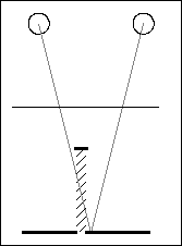
For all practical purposes my method of hidden surface removal is at least as good as any other, and much faster. In fact because it works directly on the links it is absolutely guaranteed to prevent multiple links and the associated artifacts. With traditional hidden surface algorithms there is always the chance that rounding errors will allow a few multiple links to slip through. Recall that we originally specified the depth as an array of unique z-values, z(x,y). It is usual when programming the older hidden surface removal method to assume the scene extends from the defined points all the way back to infinity. In contrast, my method effectively takes the scene as comprising only sections of planes parallel to the screen as defined in the array. In extreme geometrical cases (e.g. object less than a quarter of an inch wide in front of a background some 7 inches or more behind) it would be possible observe some of the background to either side of the object with the ray to one eye going behind the object (see figure 3). The background directly behind the object, though technically visible to both eyes, is inherently given undefined depth by the algorithm described and might appear as a hole in the background. This situation is extremely rare, and still does not cause any other defects in the image.

Figure 3: Extreme geometrical case where it is revealed that the
scene does not extend back to infinity from the front surfaces.
The pattern must be at least as wide as the maximum stereo separation otherwise there is a problem. You cannot just loop around and begin the pattern again because the repeat will be interpreted by the observer as three-dimensional information and artifacts will result - visible fragments of 3D surfaces that weren't supposed to be there. If the chosen pattern is designed to "tile" then to optimise the matching the stereogram paramters can be adjusted and/or the pattern resized in advance so that the pattern width is equal to the maximum stereo separation.
When applying the pattern from left to right, new pixels have to be inserted where parts of the object are seen by the right eye only. These regions of the picture have undefined depth, but given no other information the brain often associates them with the farther depth (this occurs with RDS). However, there can be a problem with patterned stereograms if the new pattern obviously doesn't match up: lone inserted pixels tend to float and twinkle, and larger sections may appear as a "hole" in the image. There is no easy solution to the "hole" problem, although its severity depends on the pattern used, and tends only to be a problem if you look for it!
In reality, a gently receding slope is visible to both eyes, though one eye will see the surface detail slightly stretched compared to the other. For the stereogram where smooth slopes have been quantized as a sucession of many flat sections, there will be a lone pixel visible only to one eye inserted on the edge on the edge of each step. It is these which can twinkle if new colours are used because the brain expects both eyes to be seeing the same thing, albeit with a small distortion, and "retinal rivalry" occurs. My solution to this problem is to copy the colour of an adjacent pixel in these circumstances.
At real depth-disjoints in the 3D image it is necessary to insert new sections of pattern. However these must not duplicate pattern already used on that line of the stereogram otherwise artifacts arise in the 3D scene akin to those we removed with hidden surface removal. I chose to fill-in using pattern taken from a number of lines higher or lower than the current line. Experiment showed that vertical offsets in increments of 1/16th inch are quite adequate to prevent the observer's brain making incorrect associations, and hence eliminate artifacts.
A few new variables and arrays are introduced at the start of the program:
 int ydpi=75;
 int yShift=ydpi/16;
 int patHeight=patternbmp->GetHeight();

 int maxdepth=12*xdpi; // maximum depth used

 int maxsep=(int)(((long)eyeSep*maxdepth)/(maxdepth+obsDist)); // pattern must be at
                                                               // least this wide
 int lastlinked;
The linking and plotting processes are identical to last time, but the third
(pattern-applying) for(x...) loop is replaced by that below which uses the
pattern rather than random-dots.
  lastlinked=-10; // dummy initial value

  for (x=0; x<width; x++)
  {
   if (lookL[x]==x)
   {
    if (lastlinked==(x-1)) colour[x]=colour[x-1];
    else
    {
     colour[x]=GetPixelFromPattern(x % maxsep,
                                   (y+(x/maxsep)*yShift) % patHeight);
    }
   }
   else
   {
    colour[x]=colour[lookL[x]];

    lastlinked=x; // keep track of the last pixel to be constrained
   }
  }
where
New variables:
  oversam	= oversampling ratio ie. ratio of virtual pixels to real pixels
  vwidth	= the new `virtual' width
  veyeSep	= eye separation in `virtual' pixels
  vmaxsep	= maximum stereo separation in 'virtual' pixels
Here is the full program:
 int patHeight=patternbmp->GetHeight();

 const maxwidth=640*6;  // allow space for up to 6 times oversampling
 int xdpi=75; int ydpi=75;

 int yShift=ydpi/16;

 int width=640;
 int height=480;

 int oversam=4; // oversampling ratio
 int lookL[maxwidth]; int lookR[maxwidth];
 COLOUR colour[maxwidth], col;
 int lastlinked; int i;

 int vwidth=width*oversam;

 int obsDist=xdpi*12;
 int eyeSep=xdpi*2.5; int veyeSep=eyeSep*oversam;

 int maxdepth=xdpi*12;
 int maxsep=(int)(((long)eyeSep*maxdepth)/(maxdepth+obsDist)); // pattern must be at
                                                               // least this wide
 int vmaxsep=oversam*maxsep

 int featureZ, sep;
 int x,y, left,right;
 BOOL vis;


 for (y=0; y<height; y++)
 {
  for (x=0; x<vwidth; x++)
  { lookL[x]=x; lookR[x]=x; }

  for (x=0; x<vwidth; x++)
  {
   if ((x % oversam)==0) // SPEEDUP for oversampled pictures
   {
    featureZ=<depth of image at (x/oversam,y)>

    sep=(int)(((long)veyeSep*featureZ)/(featureZ+obsDist));
   }

   left=x-sep/2; right=left+sep;

   vis=TRUE;

   if ((left>=0) && (right<vwidth))
   {
    if (lookL[right]!=right) // right pt already linked
    {
     if (lookL[right]<left) // deeper than current
     {
      lookR[lookL[right]]=lookL[right]; // break old links
      lookL[right]=right;
     }
     else vis=FALSE;
    }

    if (lookR[left]!=left) // left pt already linked
    {
     if (lookR[left]>right) // deeper than current
     {
      lookL[lookR[left]]=lookR[left]; // break old links
      lookR[left]=left;
     }
     else vis=FALSE;
    }
    if (vis==TRUE) { lookL[right]=left; lookR[left]=right; } // make link
   }
  }

  lastlinked=-10; // dummy initial value

  for (x=0; x<vwidth; x++)
  {
   if (lookL[x]==x)
   {
    if (lastlinked==(x-1)) colour[x]=colour[x-1];
    else
    {
     colour[x]=GetPixelFromPattern((x % vmaxsep)/oversam,
                                   (y+(x/vmaxsep)*yShift) % patHeight);
    }
   }
   else
   {
    colour[x]=colour[lookL[x]];

    lastlinked=x; // keep track of the last pixel to be constrained
   }
  }

  int red, green, blue;

  for (x=0; x<vwidth; x+=oversam)
  {
   red=0; green=0; blue=0;

   // use average colour of virtual pixels for screen pixel
   for (i=x; i<(x+oversam); i++)
   {
    col=colour[i];
    red+=col.R;
    green+=col.G;
    blue+=col.B;
   }
   col=RGB(red/oversam, green/oversam, blue/oversam);

   SetPixel(x/oversam,y, col);
  }
 }
Note that the depth information required (in the featureZ= line) is still
measured in units of the width of a whole pixel.
Resolution enhancement makes stereograms quite acceptable on an ordinary medium-resolution monitor by smoothing away the harsh depth-steps. To achieve ultimate high-definition and greater clarity stereograms still need to be created for better resolution display devices (such as laser printers).
Practical points on the use of in-between colors
If the display device supports 15- or 24-bit colour (32768 or 16.7million colours) then displaying in-between colours presents no difficulty. However, many common displays use a palette of just 256 colours. Provided there is a good tonal range in the palette of the original pattern then the nearest available colour can be used in place of the ideal in-between. The process of matching nearest colours is intrinsically slow; the required calls to Windows' built-in GetNearestPaletteIndex() function can take considerably more processor time than the stereogram maths! In practice, to reduce the time taken, a lookup table would be used (by limiting the colour to 15-bit, only 32768 bytes are needed) - see special topics on colour matching and other speedups.
 int patHeight=patternbmp->GetHeight();

 const maxwidth=640*6;  // allow space for up to 6 times oversampling
 int xdpi=75; int ydpi=75;

 int yShift=ydpi/16;

 int width=640;
 int height=480;

 int oversam=4; // oversampling ratio
 int lookL[maxwidth]; int lookR[maxwidth];
 COLOUR colour[maxwidth], col;
 int lastlinked; int i;

 int vwidth=width*oversam;

 int obsDist=xdpi*12;
 int eyeSep=xdpi*2.5; int veyeSep=eyeSep*oversam;

 int maxdepth=xdpi*12;
 int maxsep=(int)(((long)eyeSep*maxdepth)/(maxdepth+obsDist)); // pattern must be at
                                                               // least this wide
 int vmaxsep=oversam*maxsep

 int s=vwidth/2-vmaxsep/2; int poffset=vmaxsep-(s % vmaxsep);

 int featureZ, sep;
 int x,y, left,right;
 BOOL vis;


 for (y=0; y<height; y++)
 {
  for (x=0; x<vwidth; x++)
  { lookL[x]=x; lookR[x]=x; }

  for (x=0; x<vwidth; x++)
  {
   if ((x % oversam)==0) // SPEEDUP for oversampled pictures
   {
    featureZ=<depth of image at (x/oversam,y)>

    sep=(int)(((long)veyeSep*featureZ)/(featureZ+obsDist));
   }

   left=x-sep/2; right=left+sep;

   vis=TRUE;

   if ((left>=0) && (right<vwidth))
   {
    if (lookL[right]!=right) // right pt already linked
    {
     if (lookL[right]<left) // deeper than current
     {
      lookR[lookL[right]]=lookL[right]; // break old links
      lookL[right]=right;
     }
     else vis=FALSE;
    }

    if (lookR[left]!=left) // left pt already linked
    {
     if (lookR[left]>right) // deeper than current
     {
      lookL[lookR[left]]=lookR[left]; // break old links
      lookR[left]=left;
     }
     else vis=FALSE;
    }
    if (vis==TRUE) { lookL[right]=left; lookR[left]=right; } // make link
   }
  }

  lastlinked=-10; // dummy initial value

  for (x=s; x<vwidth; x++)
  {
   if ((lookL[x]==x) || (lookL[x]<s))
   {
    if (lastlinked==(x-1)) colour[x]=colour[x-1];
    else
    {
     colour[x]=GetPixelFromPattern(((x+poffset) % vmaxsep)/oversam,
                                   (y+((x-s)/vmaxsep)*yShift) % patHeight);
    }
   }
   else
   {
    colour[x]=colour[lookL[x]];

    lastlinked=x; // keep track of the last pixel to be constrained
   }
  }

  lastlinked=-10; // dummy initial value

  for (x=s-1; x>=0; x--)
  {
   if (lookR[x]==x)
   {
    if (lastlinked==(x+1)) colour[x]=colour[x+1];
    else
    {
     colour[x]=GetPixelFromPattern(((x+poffset) % vmaxsep)/oversam,
                                (y+((s-x)/vmaxsep+1)*yShift) % patHeight);
    }
   }
   else
   {
    colour[x]=colour[lookR[x]];

    lastlinked=x; // keep track of the last pixel to be constrained
   }
  }

  int red, green, blue;

  for (x=0; x<vwidth; x+=oversam)
  {
   red=0; green=0; blue=0;

   // use average colour of virtual pixels for screen pixel
   for (i=x; i<(x+oversam); i++)
   {
    col=colour[i];
    red+=col.R;
    green+=col.G;
    blue+=col.B;
   }
   col=RGB(red/oversam, green/oversam, blue/oversam);

   SetPixel(x/oversam,y, col);
  }
 }
I cannot resist hinting at how I achieved some dramatic speedups, and hope to whet your appetite for the subject (which seems to be sadly neglected by many of the main-stream software companies!).
Microseconds count in the innermost loops where code may be executed over a million times. For the outer "for y..." loop, performed only hundreds of times, speed is less of an issue. Hence it always makes sense to optimise deepest loops first. Be aware that some speedups sacrifice clarity of program and may complicate any future changes to the algorithm. Note also that some speedups, particularly buffers, may decrease the performance in some circumstances. I try to balance speed against simplicity. There also comes a point when the law of diminishing returns sets in. It is easy to spend many hours of programming time trying to shave just fractions of a second off the run time!
The following give a taste of some specific speedups used in the latest version of SISGen:
In my latest program I have eliminated almost all maths in the main loop anyway by using a lookup table to relate image depth to stereo separation.
Finally, make sure any compiler options are set to optimise for fast execution - and time it - sometimes the compiler gets it wrong!
All C code is taken from working programs. However, the programs needed a degree of processing before landing on this page, so it is concievable that a couple of minor errors could have crept in! If you do find a problem, let me know!
 int maxsep=(int)(((long)eyeSep*maxdepth)/(maxdepth+obsDist)); // pattern must be at
                                                               // least this wide
with the required long type-casting. - Thanks to Armando for pointing
that one out.
for (x=s-1; x>=0; x--)
{
 if (lookR[x]==x)
 {
  ...
 }
 else
 {
  colour[x]=colour[lookR[x]];
  lastlinked=x;
 }
}
- obviously(?)! - Thanks again to Armando.All three errors probably occurred at times when these listings were ammended to reflect improvements and simplifications made in my working Windows source code.


©1995-2001 William Andrew Steer